Original Factory 10kw Motor


Our intention should be to fulfill our consumers by offering golden provider, superior price and superior quality for Original Factory 10kw Motor, “Passion, Honesty, Sound services, Keen cooperation and Development” are our goals. We’ve been here expecting close friends all around the earth!
Our intention should be to fulfill our consumers by offering golden provider, superior price and superior quality for , Our items are widely recognized and trusted by users and can meet continuously changing economic and social needs. We welcome new and old customers from all walks of life to contact us for future business relationships and mutual success!
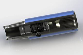
1. By-pass Assembly
It has two positions of by-pass and close. It is in by-pass position during trip operation, circulates mud fluid in the drill string into the annular space by-passing the idle motor, so that mo mud may spray out onto the platform during the trip operation. When mud flow rate and pressure reach the setting value, the valve stem moves down and closed the valve.
Meanwhile, mud stream flows through the motor, and converts the pressure energy into mechanical energy. As mud flow rate is too low, or mud pump stops, and as the created pressure is not enough to overcome spring force and static friction force, the spring presses the stem upward and by-pass is in open position. In general, the cross-over sub is used in deep well and large angle well horizontal well or hollow rotor selected.
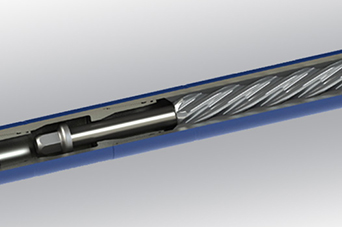
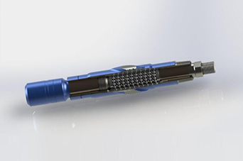
2. Motor Assembly
It consists of stator and rotor. Stator is made by squeezing rubber sleeve on the wall of steel tube. There forms spiral structure with a certain geometric parameter. Rotor is a chrome-plated screw rod.
Stator and rotor matches with each other, to form spiral line and seal cavity through their guide rail difference. With rotor running in the stator, the seal cavity is moving along its axial direction, continuously forms and disappears to complete its energy conversion. This is the basic principle of down-hole motor.
Spiral seal line on rotor is divided into single end and multi-end (stator with one more end than rotor). The less ends the motor has, the higher speed and the lower torque are. The more ends it has, the lower speed and the higher torque are. The following figure shows the sectional profile of several typical motors.
3. Adjustable Bend Housing
In drilling the non-conventional wells such as directional wells, horizontal wells, and highly-deviated wells, downhole motor with adjustable bend housing which uses the new coupling design can be adjusted from 0°to 4°at 19 different angles. It overcomes the shortcomings of flat universal shaft such as the exposed surfaces are susceptible to erosion and short operational life.
4. Cardan Shaft Assembly/Universal Shaft Assembly
The function of cardan shaft is to convert planetary motion into fixed constant rotation of drive shaft, to transmit torque and speed from motor on the drive shaft, and to the bit. Cardan shaft mostly use flat shaft, but some are flexible shafts. Our flat type shaft used on our down-hole motor is made by linear cutting technology, so the cut has high parallelism, roughness. And it doesn’t damage metal chemical composition. Thus, it has longer running life and less mechanical loss.
Down-hole motor shall be disassembled as quickly as possible after use to examine cardan shaft. If it is found out that wear degree is over maintenance standard, relevant consumable components shall be changed promptly. If it is not, down-hole motor can not be running normally due to over run time of cardan shaft.
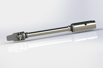
5. Drive Shaft Assembly
Drive shaft is to transmit motor rotary dynamic force onto the bit, meanwhile to withstand axial and radial load from drilling weight. We have two types of drive shafts, as follow:
i) Bit nozzle pressure loss is 7.0 Mpa, using hard alloy radial bearing and drive shaft assembly with thrust bearings.
ii) Bit nozzle pressure loss is 14.0 Mpa, using hard alloy radial bearing and PDC cutter flat thrust bearing. It has longer lasting life and higher bearing
capacity.
6. To suit different drilling request, we supply two kinds of stabilizers on the Bearing Assembly: Fixed Stabilizer and Replaceable Stabilizer.
7. Anti-Drop-Device
The safety catch sub is located between the power section and the dump valve (or crossover sub). It prevents leaving the rotor and internal motor components in the hole in the unlikely case of external connection failure in the motor string. It is generally used for extremely harsh drilling applications and where added precautions are required.